NOTE: This manual is for Light Composer v3.0 and later versions. Contact Light Conversion Support if you need assistance with earlier versions of Light Composer.
Introduction
Light Composer is an application for controlling CRONUS-3P tunable femtosecond lasers. It allows to start and shutdown the laser, set wavelength, GDD compensation and power level without worrying about the details. Light Composer also provides an API for remote control and experiment automation.

Basic operation
Run Light Composer to start using the device. See the Setup section when setting up for the first time or when hardware has been changed.
GUI overview
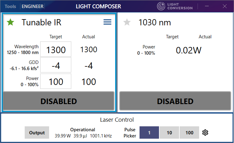
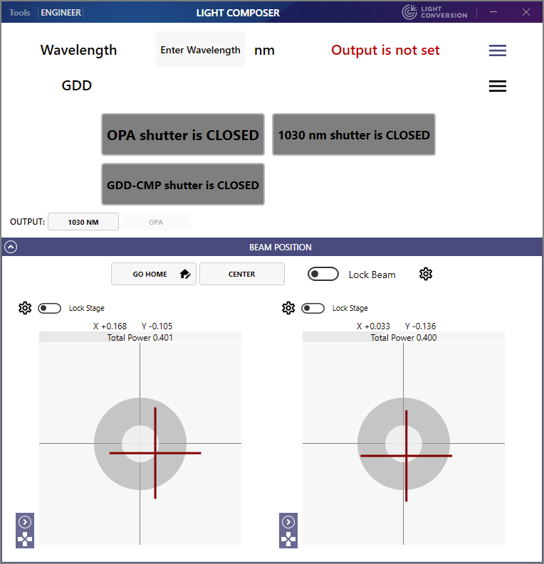
Light Composer GUI contains one or more panels for each of the available beam outputs: tunable IR, tunable SWIR and fixed 1030 nm. There's also a pump laser control widget at the bottom. Multiple channels can be operated at once, but one of the channels is selected as primary by clicking the green star. Whenever changing some channel parameters would affect another channel, the primary channel takes priority. All channels have at least an output shutter which can be used to enable or disable the output of the beam. Depending on the configuration of the laser, other channels can have tunable wavelength, GDD, power attenuation and beam steering modules.

Opening and closing shutters
The laser system typically contains several internal beam shutters and the final output shutters for respective channels. Internal shutters cannot be controlled by the user and are controlled by Light Composer whenever needed. When enabling output for respective channels, internal shutters close or open for the wanted output together with the respective final output shutter.
Final output shutter is closed during the setting procedure of wavelength and GDD parameters in case when the tunable output is enabled. Once the procedure is completed, final output shutter is opened thus enabling the output.
More advanced shutter controls are available in Engineer level. Contact Light Conversion support to get the access to the Engineer level controls.
Setting wavelength
To set the output wavelength in the tunable output channel, enter the required value in nanometers in the Wavelength field and press Enter. Once entry is confirmed Light Composer will start the wavelength set procedure and GUI will show the setting progress along with a notice message for the particular interaction. Message will appear if the interaction is used for the first time.
If the beam steering is enabled an alignment cycle will be initialized to center the output beam. While beam steering is in progress the Center button in the Beam Position panel will change to Cancel Centering with a rolling progress bar. Depending on the beam steering configuration, the alignment cycle may start during wavelength setting or after the wavelength and GDD have been set.
Setting GDD
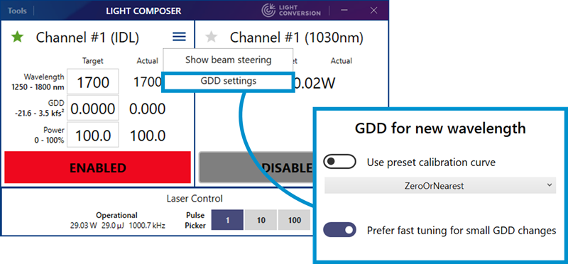
To set GDD compensation (only for tunable IR output), enter the required value in fs2 in the GDD field and press Enter. In order to tune the GDD without disabling the output, click on the Prefer fast tuning for small GDD changes switch button in the GDD settings. The GDD value can then be changed by positioning the cursor at the hundreds or tens digit and using the up/down keyboard arrows.
GDD setting can be accessed through the dropdown menu of the tunable IR output channel, see figure below.
Switching between channels
CRONUS-3P can switch between different output channels depending on device configuration. The primary channel is indicated by a green star. Shutters on all channels can be open at any time, but the parameters of the beam will change depending whether it is primary or not. For example, Tunable IR and Tunable VIS channel wavelengths are tied together, you can set the wavelength of the primary channel and the nonprimary channel wavelength will change accordingly. Channel panels can be disabled in Light Composer configuration if needed.
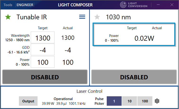
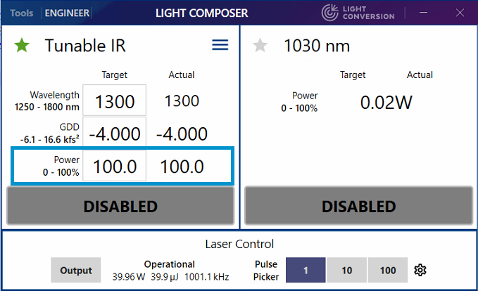
When a tunable channel is primary the 1030 nm output can only emit a small residual fraction of the pump beam, usually <50 mW. The available residual power is shown in the 1030 nm panel when the 1030 nm output is not primary (e.g., 20 mW in the example below).
NOTE: Residual power level is set at factory during production. Contact Light Conversion support if you need to change this value.
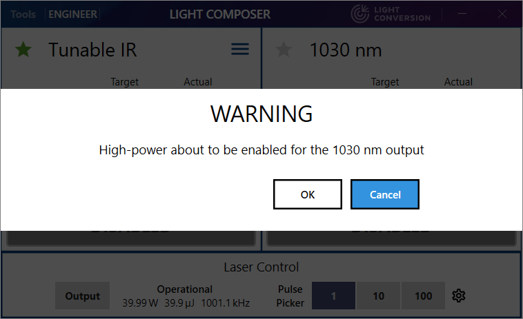
The full power 1030 nm beam (usually 40 W) can be accessed by clicking the grey star and setting the 1030 nm as primary.
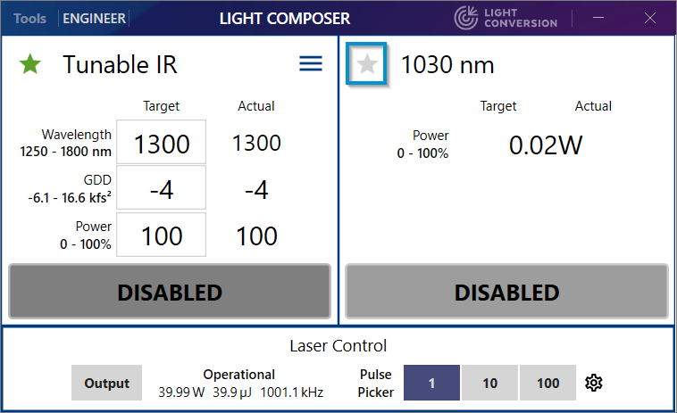
You will be presented with a warning dialog. Make sure your setup can safely handle the high power beam. In particular, make sure that the CRONUS-3P 1030 nm port plug is removed and that the beamline is terminated by a suitable beam dump.
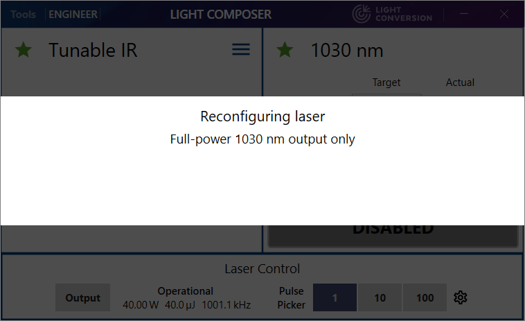
A dialog will be shown while the OPA interface is being reconfigured for 1030 nm output only.
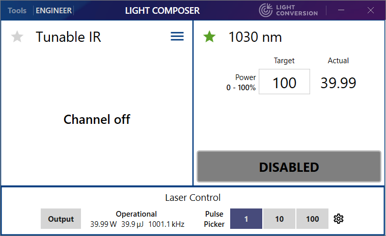
Once CRONUS-3P is configured for high-power 1030 nm output the tunable channels are disabled and the 1030 nm output attenuator control is enabled.
Output power control
Use the Power row controls to control the output power of individual channels. Use the Target field to set the desired value in percent and press Enter.
Systems having additional tunable outputs can also have additional attenuators for those outputs. If an additional tunable attenuator is installed their target power levels can be set independently.
Controlling the power of the 1030 nm output
The 1030 nm output operates in residual low-power mode when not primary or high-power mode when primary.
The residual 1030 nm output has no attenuator control and can only be enabled or disabled. It is available when any of the tunable channels is primary.
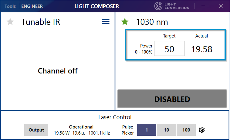
High-power 1030 nm output has attenuator control, the Target value is set in percent and the Actual value is shown in watts as reported by the internal power sensor of the laser.
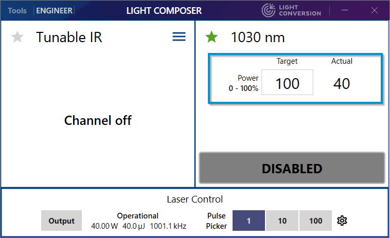
For example, setting 50% emits 20 W.
Controlling tunable output power with an external voltage signal
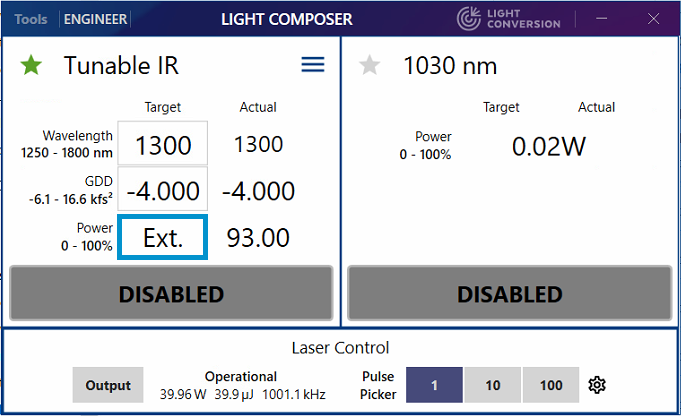
To control the output power of the Tunable IR channel using an external voltage signal connect the signal to the AV (pin 24) input of the XS13 port breakout cable and enable External analog control in the External attenuator menu.
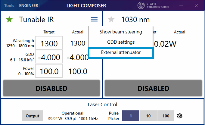
When external control is enabled, the Target field changes to Ext. and the Actual field shows the current attenuator value. The field updates slower than the actual attenuator transmission.
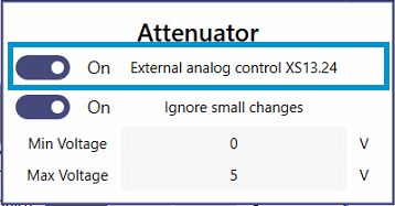
Some attenuator parameters can be set in the attenuator menu. All parameters can be found in the Channel Editor under ExternalAttenuatorSettings or in the ExternalAttenuatorControl.json configuration file of the respective channel. The available parameters are:
MinVoltage- Control voltage that corresponds to 0% output.MaxVoltage- Control voltage that corresponds to 100% output.IsControlEnabled- True if external control is enabled.UpdateFrequencyHz- Feedback control loop frequency in Hz.IgnoreSmallInputChanges- Ignores small voltage fluctuations on the external control signal to prevent excessive attenuator motor wear, especially when external control is always on. The threshold to ignore isSmallInputThresholdAdu.InputAduPerVolt- Voltage conversion factor of the external analog input. Default is 2625.SmallInputThresholdAdu- External control signal fluctuation suppression threshold in adu. A reasonable value for shielded BNC cable input is 5.
Tunable VIS output attenuator cannot be controlled using an external voltage.
Output presets
Output presets are combinations of wavelength, GDD and output power that can be set in one click. Using an output preset also triggers only a single beam steering cycle. You can use presets to quickly change between two output wavelengths with their GDD settings and power levels, or to change between several GDD values at the same wavelength. To open the output preset menu, click the Channel Menu and select Output Presets.
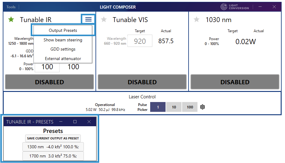
Click the Save current output as preset button to create a new preset. Left-click the preset button to select a preset, right-click it to delete it.
Presets are currently available for the Tunable IR channel only.
Laser warm-up behavior
When the laser output is disabled and enabled again there is a warm-up period during which the power and the beam pointing can change as the device warms up. This occurs when one of the output shutters is open for the first time after a period of inactivity. It also happens when the laser is turned on after being put to standby, especially if the chiller was switched off as well.
The time it takes for the laser to warm-up after standby depends on environmental conditions, chiller placement, and coolant hose length. The pump laser waits for its temperature-critical parts to reach the right temperature, so once the laser has started nominal 1030 nm output power should be available immediately, and beam pointing should typically stabilize within 60 minutes.
When all output channels are disabled the pump laser output is also disabled to conserve the lifetime of the OPA. When any of the output shutters are enabled for the first time after a period of inactivity, the output power will stabilize within the 1% average output power specification in approx. 10 – 15 min. Opening and closing the shutters, changing the pulse-picker divider, using external gating, etc. can cause the output power and beam pointing to change for a brief period.
The OPA can be kept warmed up for some time between periods of beam output in order to reduce output power and beam pointing variation by allowing the pump laser to remain enabled when no outputs are being emitted. A new Keep OPA Warm (KOW) menu has been introduced in v3.1 to achieve this function.
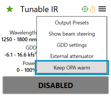
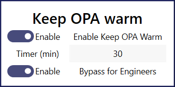
Keep OPA warm behavior has the following options: - Enable Keep OPA Warm toggle turns the KOW function on and off - Timer (min) is the number of minutes the OPA is kept warm when all output shutters are closed - Bypass for Engineers toggle bypasses the KOW function for the Engineer access level without affecting the User and Advanced levels
KOW configuration parameters are stored in Main.json.
[LightComposer/Main.json]
{
  ...
  "KeepOPAWarm": true,
  "KeepOPAWarmForEngineers": true,
  "KeepOPAWarmTimerMinutes": 30
}
If KOW is enabled, the OPA shutter will remain open for a period of time set by KeepOPAWarmTimerMinutes (default 30 min) even after all output channel shutters are closed. During the KOW period the OPA will continue to be pumped and stay optimally warmed up. If any of the the output shutters are open before the timer expires the output power and beam pointing should remain constant. If the the timer expires the OPA shutter closes and the pump beam is disabled to conserve mains power and the OPA crystal lifetime. KeepOPAWarmTimerMinutes can be adjusted to suit particular experimental needs.
The KOW function can be disabled in Engineer mode for troubleshooting and service purposes without affecting its operation in Basic and Advanced modes.
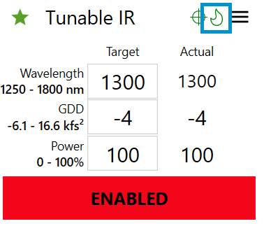
A fire icon shows the status of the KOW function. A separate icon is displayed for every tunable channel, but currently they all show the same state. When the OPA is warm, i.e., the KOW function is active or the output shutter is open the flame is green.
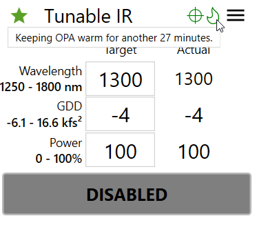
When the shutter is closed the flame remains green while the KOW timer is running. You can check the remaining time by hovering over the flame icon:
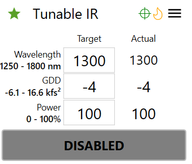
When the timer has expired the OPA shutter will close and the flame icon will turn orange indicating that the OPA is now cold.
You can also check the KOW activity in the log. While KOW is active the log will contain messages with the time remaining:
Once the KOW timer has expired the log will show:Beam steering
Usage considerations
A beam steering module is installed for the Tunable IR beamline in most CRONUS-3P systems. The purpose of the module is to correct changes in output beam position and pointing during wavelength and GDD changes, as well as to correct long-term beam drift. When beam steering is enabled, the beam is centered whenever Light Composer starts (if a startup preset is enabled, which it is by default), and when wavelength or GDD are changed. The beam steering motors can also be moved manually, e.g., to optimize beam position based on the observed signal.
The beam steering module itself has a steering accuracy limit and in some cases where the output beam parameters remain mostly fixed it might be better to disable automatic beam steering.
Automatic beam steering
For channels with beam steering a panel can be opened by selecting Show beam steering in the Channel Menu. This will open a separate beam steering panel which can be used to configure and track beam steering behavior.
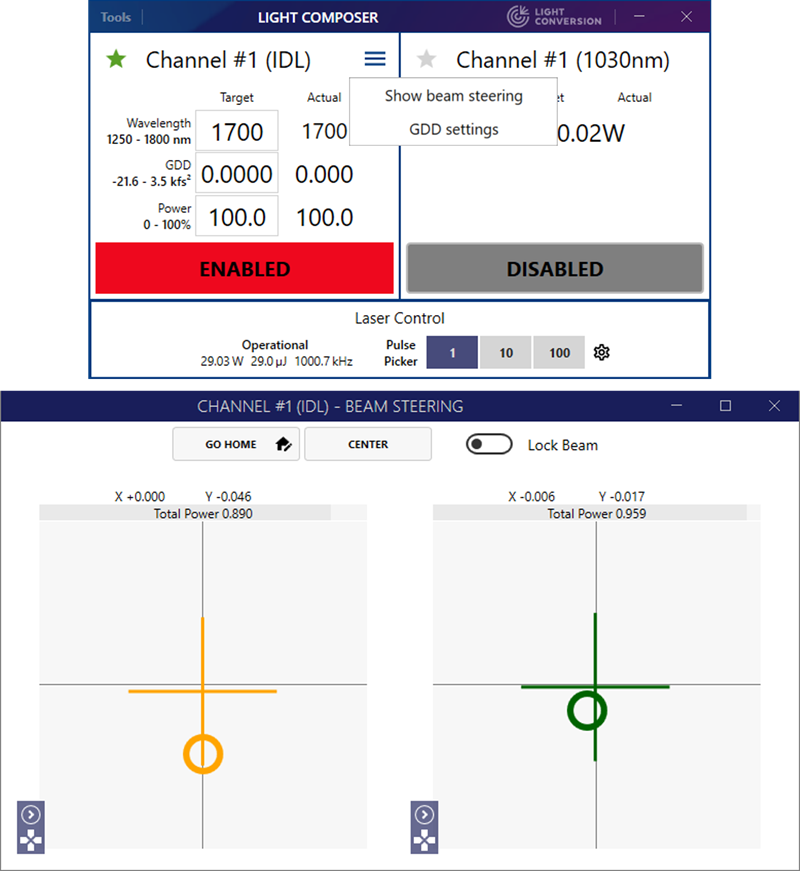
The beam steering panel contains several buttons as well as two subpanels which show the near- and far-field beam position. The buttons have the following functions:
- Go Home - moves the beam steering mirrors to their home positions, which is useful if beam position tracking is lost entirely.
- Center - triggers a beam alignment cycle.
- Lock Beam - keeps the beam centered continuously by triggering beam steering whenever the beam leaves the inner target area on at least one of the sensors. Note: this is an advanced feature that might not work for all beam steering configurations.
The Manual Control button at the bottom left of the beam sensor widgets opens a control for direct beam steering motor control which allows the mirrors to be moved manually.
Manual beam steering
The positions of the beam steering mirrors can be adjusted in the Beam Steering panel by clicking on the expand arrow of the Manual Control button at the bottom left of the beam position widget. The motor positions can then be adjusted by dragging the sliders or entering the position value. The position value is in arbitrary units and the 0 - 100 range covers the entire movement range of the beam steering mirror.
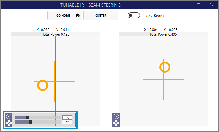
The two beam steering mirrors provide four degrees of freedom to adjust the position and pointing of the beam. It is best to use the second (right subpanel) mirror to compensate a slight beam pointing misalignment as it will mostly affect the pointing of the outgoing beam. Both mirrors can be used to walk the beam and to to correct its pointing if the misalignment is more severe.
If manual adjustment made the beam pointing worse, you can click Center to initiate an automatic adjustment cycle. You can also return to a predefined home position by clicking Go Home. If there is no predefined home position before you start manual beam adjustment, it is recommended to click the Set Home button (the house icon nested in the Go Home button). The current position is then saved and you can always return to it by clicking Go Home.
Enabling and disabling beam steering
Automatic beam steering after wavelength and GDD changes can be disabled by setting IsEnabled to False under Output Beam Stabilization Settings. Position sensors will still display the beam position and manual control can still be used to move the beam steering mirrors.
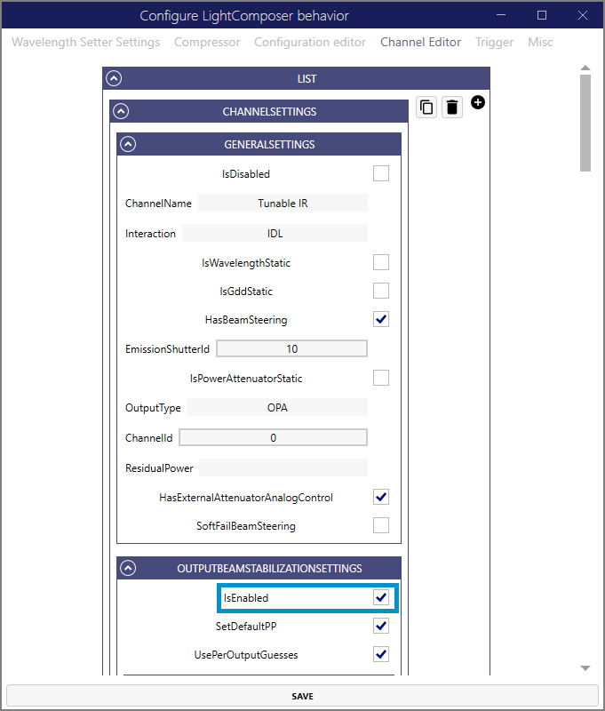
To disable the beam steering function altogether set IsEnabled to False and HasBeamSteering to False under General Settings.
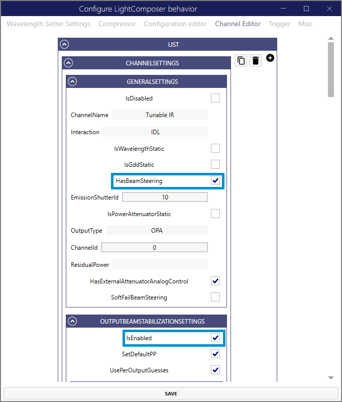
These options can be set for each channel separately if there are multiple beam steering modules installed.
Triggering
The triggering configuration panel is located under Tools->Edit configuration->Trigger.
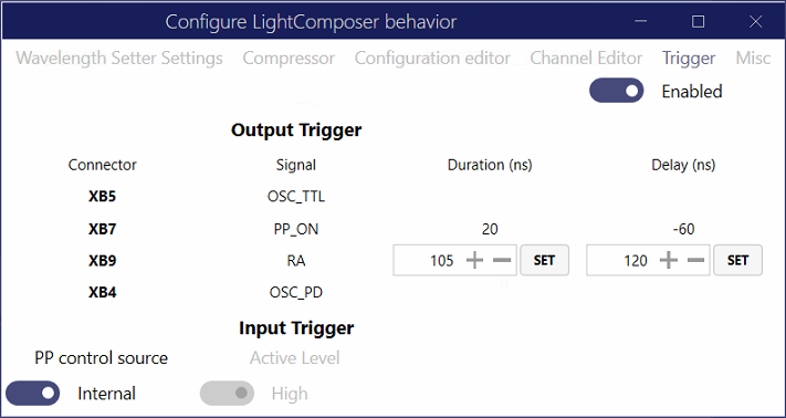
All trigger functions can be enabled or disabled using the toggle switch at the top right. Triggering is enabled by toggling the switch, which configures the input and output ports. If triggering is enabled configuration is applied at app startup as well.
The following output triggers are available:
- XB5 - Digital oscillator signal (OSC_TTL) which is derived from the laser oscillator. This ~66 MHz signal is phase locked to all optical and electronic outputs and can be used e.g. when a high-frequency digitizer PLL clock is required for the 1 MHz laser output.
- XB7 - Pulse picker output (PP_ON) signal which is emitted 60 ns before the amplified optical pulse and can be used to synchronize detectors or other equipment that must be triggered before the arrival of the optical pulse. The PP_ON signal is only emitted if the optical pulse is emitted, i.e. the rate of PP_ON is reduced if a PP divider or pulse gating is used. PP_ON is also disabled when the amplified output is disabled. The PP_ON output is synchronized to all tunable outputs and the amplified 1030 nm output.
- XB9 - Regenerative amplifier (RA) signal which is derived from the amplification cavity. This signal is locked to the base repetition rate of the laser and is always on. The RA TTL signal duration and delay can be configured to shift the electronic pulse with respect to the optical pulse. This output is also not disabled during output pulse gating or when outputs are disabled. This is useful, e.g. when a clock for a digitizer or an external PLL must not be interrupted during blanking.
- XB4 - Analog oscillator photodiode signal (OSC_PD) which can be used when a higher speed oscillator signal is needed.
Input triggering can be used to gate the pulse picker using an external TTL source. When an external PP control source is selected a pulse is only emitted when the external signal is high (or low, as set by Active Level). Note, the pulse picker operates at the RA rate and input triggering can only reduce this rate by gating. It cannot change the RA base rate or pulse timing. If the external gate is not synchronized to the RA the gate phase will likely slip with respect to the RA pulse train and sometimes instead of the desired Nth pulse the N + 1st pulse will be emitted with a maximum jitter of 1/RA rate, typically 1 µs. To avoid this effect the external gate should be first locked to the RA clock and then gated to control the PP.
Troubleshooting
Unresponsive laser and full system reboot
If Light Composer or the laser become unresponsive follow the procedure below. Check if the problem is resolved after each step. - Restart Light Composer - Restart the Topas4 server - Soft-reboot the laser by putting to standby and starting again - Reboot the control computer - Cold-reboot the laser by putting to standby, turning the PSU key off, waiting a few seconds, and starting again
If not even a cold reboot helps to establish laser control contact support.
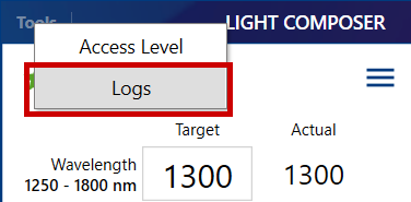
Accessing Light Composer logs
Application logs can be accessed by selecting Logs in the Tools menu.
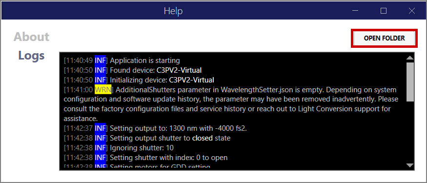
The log for the current session will be shown in the Logs window. Clicking Open Folder shows all logs.
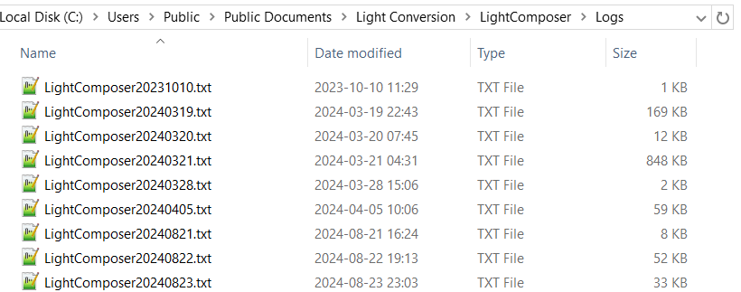
Logs are named according to the current date.
Attenuator transmission is incorrect when set using external analog control voltage
If the attenuator transmission is set to a wrong level when a certain external analog control voltage is applied, the InputAduPerVolt, MinVoltage, or MaxVoltage parameters might be incorrect.
The InputAduPerVolt parameter defines the conversion factor of the external voltage into adu units that are used to calculate the target transmission of the attenuator. The default value is 2625. This value can be adjusted to compensate for voltage loading effects, e.g., if the voltage source cannot supply sufficient current or is branched out to additional equipment (a scope or a DAQ).
The voltage range that is mapped to 0 - 100% attenuator transmission is defined by MinVoltage and MaxVoltage parameters. The default values are 0V and 5V, respectively. This range can be adjusted to suit the expected input voltage range.
Typically, when InputAduPerVolt is set to 2625 and the configured voltage range is 0V to 5V, supplying 0V should set the attenuator to 0% and 5V should set 100%. Contact Support if this is not the case.
Setup
Obtaining laser control software
The CRONUS-3P comes with a USB drive which contains device control software and utilities. Contact Support if you no longer have access to the drive.
Links to download the most recent software are provided below. However, it is advised to use the software provided in the USB drive for a specific device, especially a custom one.
To control a CRONUS-3P you will need: - Light Composer – CRONUS-3P end-user application - Topas4 – device control server, typically installed together with WinTopas4 though the latter isn't necessary
It is useful to also have the following: - WinTopas4 – low-level OPA control software for engineers and power users - CARBIDE User App – CARBIDE laser end-user application for direct laser control - IP Assistant – utility to configure IP addresses of Ethernet adapters
Device configuration file
A device configuration file is also required. A factory configuration file is provided in the USB drive. Note, that the configuration gets updated during certain service actions which make the factory file invalid. The computer used to control the CRONUS-3P contains the current device configuration which can be obtained manually or using WinTopas4. Make sure to move the configuration file when changing computers or performing significant hardware upgrades. Contact Support if you've lost your configuration file, we should have a backup.
Configuring the Ethernet adapter
Before first launch and whenever Ethernet adapters are changed (e.g., a different USB to Ethernet adapter is used) a correct IP address needs to be configured for the adapter going to the CRONUS-3P. This step will usually be performed during installation. If you need to reconfigure the IP address, you can do so in two ways: - Easy way: use IP Assistant to set the IP address and subnet mask automatically. Select OPA under Common configurations and click Set. - Manual way: set IP address to 10.1.11.11/16 in the Windows Control Panel.
Note: the above IP address configuration is typical. Some network configurations might restrict the use of the 10.0.0.0/8 subnet or the required 10.1.0.0/16 network might already be used. When multiple Light Conversion devices are connected to the same computer the configuration will be more complex. The point is that every Ethernet adapter needs to be configured in a way that allows the control computer to reach the laser devices which have fixed IP addresses, which are listed in the device configuration files. Your local IT admin should be able to help to do it right.
Running the software
You only need to run Light Composer to control the CRONUS-3P, it will start the necessary Topas4 server instance automatically.
Power users might find running WnTopas4 also useful for advanced tasks. Note that WinTopas4 cannot adjust the GDD compressor of the CRONUS-3P. Changing the wavelength in WinTopas4 will make the GDD precompensation value undefined.
Updating Light Composer
Whenever a new version of Light Composer is available a notification will appear in the title bar. Clicking on the Update is ready button will bring up a dialog showing the current and available app versions, as well as a link to the release notes.
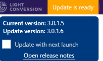
The update will not be installed automatically unless the Update with next launch is ticked and the app is restarted.
Advanced operation
Entering Advanced user and Engineer modes
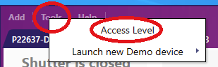
To enter the Advanced user mode go to Tools -> Access level and enter password 1600. The password for Engineer mode will be provided by Light Conversion support when needed. To return to Basic user mode enter any value to the password field. Which options are available in Advanced user and Engineer modes depends on system configuration.
Editing configuration
Light Composer configuration can be edited in several ways. Accessing configuration in the GUI requires Engineer mode. Configuration files can be edited by anyone with write access to the C:\Programs folder. Configuration changes (either via GUI or by directly editing the json files) should be made by qualified personnel only. Improper changes can make the laser unsafe, degrade its performance, render it inoperable or cause damage to downstream devices. Users are encouraged to make a backup before modifying the configuration.
The Edit Configuration menu
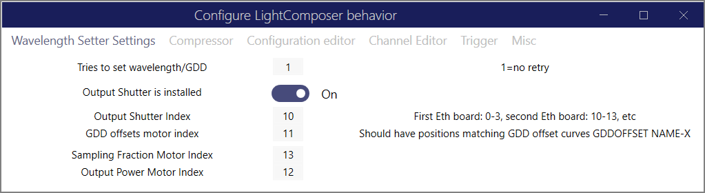
The Edit Configuration submenu can be accessed from the Tools menu in Engineer mode.

The Edit Configuration menu contains the following tabs: Wavelength setter settings, Compressor, Configuration editor, Channel editor, Trigger and Misc.
Editing JSON configuration files directly
Light Composer configuration files reside in the following folder:
C:\Programs\WinTopas4\Resources\SelfHostedServer\[Device SN]\Configuration\Settings
where [Device SN] is the serial number of the device, e.g., P24001.
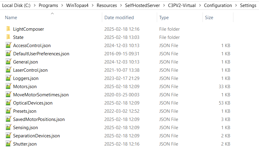
These files can be inspected and modified using any text editor. Light Composer needs to be restarted for changes to JSON files to take effect.
Configuration structure
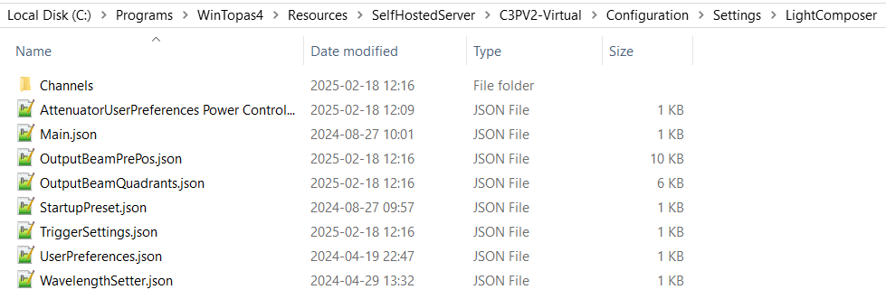
Light Composer configuration is stored in the LightComposer subfolder. Root JSON files control behavior common to all channels, and individual channel configuration can be found in the Channels folder.
The Settings folder contains a number of files that are part of the Topas4 configuration of the underlying OPA device. This configuration is explained in the WinTopas4 documentation. Light Composer and Topas4 share a similar configuration structure.
The motor indices referred to in the configuration correspond to the MotorBoardIndex values in the Motors.json file. Shutter indices are defined in the Shutter.json file.
Main.json
Main.json contains the main configuration parameters which differentiate a bare OPA (IOPA or an ORPHEUS) from a CRONUS-3P.
"OutputBeamStabilization": "None",
"OutputBeamStabilizationFirstMotorIndex": 16,
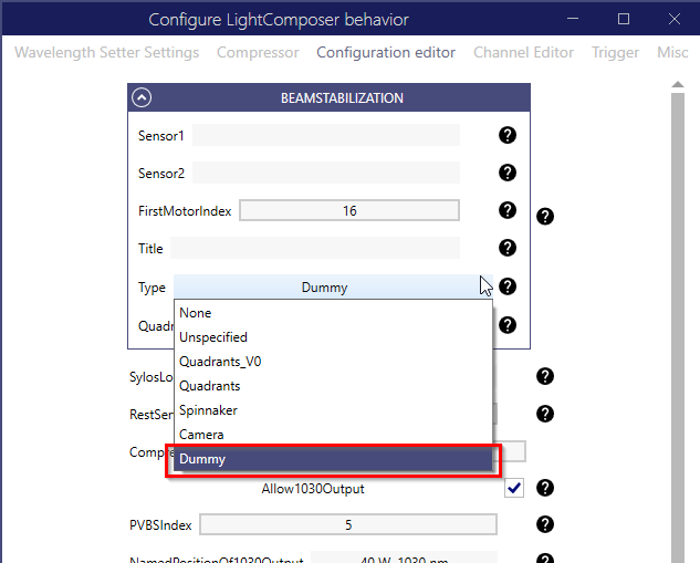
"BeamStabilization": {
"Sensor1": "",
"Sensor2": "",
"FirstMotorIndex": 16,
"Title": "",
"Type": "Quadrants_V0"
},
"SylosLogsRoot": "C:\\OPALogs\\P22624",
"RestServicesPort": 35120,
"CompressorMixerIndex": 1,
"Allow1030Output": true,
"PVBSIndex": 5,
"NamedPositionOf1030Output": "1030 nm",
"Attenuators": [
{
"Id" : 0,
"Type": "MotorSuperUnits",
"MotorIndex": 12,
"Name": "Power Control",
"IsUserVisible": true
},
{
"Id" : 1,
"Type": "MotorSuperUnits",
"MotorIndex": 20,
"Name": "Power Control SIG",
"IsUserVisible": true
}
],
"Version": "2.0.1.0",
"SystemVersion": "",
"PrimaryChannelMessage" : "Full-power 1030 nm output only",
"SecondaryChannelMessage" : "Tunable output only",
"IsDemo": true,
"KeepOPAWarm" : true,
"KeepOPAWarmTimerMinutes" : 1
}
Parameters:
- OutputBeamStabilizationFirstMotorIndex - index of first beam stabilization motor. Value must be the same as FirstMotorIndex below.
- Beam Stabilization
- FirstMotorIndex - index of first beam stabilization motor. Value must be the same as OutputBeamStabilizationFirstMotorIndex.
- Type - beam stabilization sensor type: None or Quadrants_V0
-
SylosLogsRoot- folder to store device logs -
Attenuators- list of attenuators installed in the system Id- attenuator ID used in channel configuration to select an attenuator for a given channelType- alwaysMotorSuperUnitsMotorIndex- index of attenuator motor which must map to a valid Topas4 motor configurationName- attenuator name used in UI and logs. Do not include the word attenuator in the name.IsUserVisible- if true, attenuator control will be visible to the user.PrimaryChannelMessage- user message when PVBS motor goes to 1030nm named position.SecondaryChannelMessage- user message when PVBS motor goes to OPA named position.IsDemo- if true, simulate a virtual device without connecting to real hardware; a Virtual label will be added to the app bar for indication.KeepOPAWarm- if true, OPA will be kept warm after the output shutters are closed. This is achieved by leaving the OPA pump shutter open while keeping the output shutters closed forKeepOPAWarmTimerMinutes. This parameter is ignored in Engineer mode.KeepOPAWarmTimerMinutes- how many minutes the OPA pump shutter will remain open ifKeepOPAWarmis enabled.
WavelenghtSetter.json
Beam parameter (e.g., wavelength, GDD) and output beam steering settings.
Note: GDD calibration uses WinTopas4 curves in a special way as described in internal documentation
  "TriesToSetWavelength": 1,
  "OutputShutterIndex": 11,
  "HasOutputShutter": true,
  "OutputBeamStabilization": {
    "IsEnabled": true,
    "SetDefaultPP": false,
    "UsePerOutputGuesses": false,
    "ValidRanges": []
  },
  "GDDMotorIndex": 7,
  "AdditionalShutters": [],
  "SamplingFractionMotorIndex": null,
  "OutputPowerMotorIndex": null,
  "FastTuneGDDThreshold" : 100
Parameters:
-
TriesToSetWavelength- number of attempts to set output beam parameters after each user request. The default is 1. A value greater than 1 might be useful when beam stabilization fails occasionally or there are other intermittent problems. -
HasOutputShutter- true if the system has an output shutter installed after the beam steering module. The purpose of the output shutter is to protect downstream equipment from damage during beam steering or if something fails. The output shutter is closed during beam setting and only opens if the setting procedure is successful. Systems without an output shutter are rare. -
OutputShutterIndex- index of the output shutter. -
OutputShutterStabilization- beam stabilization parameters -
IsEnabled- automatic beam stabilization is enabled and will trigger after every wavelength and GDD change -
SetDefaultPP- if true, beam stabilization will be performed by setting PP to 1. If a PP value other than 1 was used before the setting procedure, PP will be set to 1 before beam steering and set back to the previous value before opening the output shutter. This ensures that beam steering is performed at the nominal repetition rate irrespective of the PP value used when the output shutter is open. -
UsePerOutputGuesses- try to guess optimal beam steering motor values based on previous experience- True: Light Composer will learn optimal beam steering mirror positions for a given output configuration (wavelength, GDD, etc.) with each successful beam steering attempt. When a similar output configuration is requested again, the motors will move to the expected position before enabling feedback to speed up steering. The mirrors will start from the current position if there are no learned positions for the requested configuration or if all available learned positions are for parameter sets that are too different.
- False: mirrors will move to the global home before enabling beam steering. If a global home position is not set, the mirrors will start from the current position.
-
GDDMotorIndex- index of the GDD plate drum motor. -
FastTuneGDDThreshold- maximum GDD change for which fast GDD tuning still applies. Default is 500 fs2
Legacy parameters:
-
AdditionalShutters- A list of additional shutters that must be opened during wavelength setting for the beam steering phase. This list must include the GDD-CMP shutter for C3Pv1 systems, C3Pv2 systems do not need this parameter at all. The output shutter in particular must not be included for C3Pv1 systems. This shutter must be opened after beam steering and one of its functions is to protect the user and devices down the beamline during the beam steering process. -
ShuttersTolgnore- list of shutters that are not affected by the wavelength setting procedure (e.g., residual 1030 nm output from the pump laser). The output shutter should not be included in this list.
UserPreference.json
User preferences which do not affect hardware configuration.
AttenuatorUserPreference\<Name>.json
User preferences for a particular attenuator Name which do not affect hardware configuration.
OutputBeamQuadrants.json
Beam steering settings for the Quadrants_V0 type. All parameters are also accessible in Configuration Editor when in Engineer mode.
Output channels
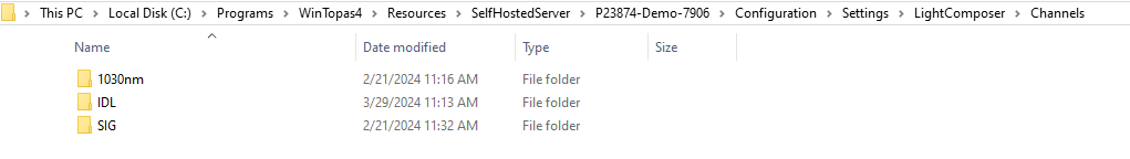
Multiple physical beam channels are represented as subfolders in the Channels folder. In the example below, there are three channels for Idler (IDL), Signal (SIG) and 1030 nm outputs. Channels can be deleted by deleting the respective channel folder.
Each channel subfolder must at least contain a valid General.json file with the following structure:
{
  "ChannelId" : 0,
  "IsDisabled": false,
  "ChannelName": "Tunable IR",
  "Interaction" : "IDL",
  "IsWavelengthStatic" : false,
  "IsGddStatic" : false,
  "HasBeamSteering" : true,
  "EmissionShutterId" : 10,
  "IsPowerAttenuatorStatic" : false,
  "AttenuatorId": 0,
  "OutputType" : "OPA",
  "HasExternalAttenuatorAnalogControl": true
}
Where:
ChannelId- channel index which is used to arrange control panels in the GUI from left to rightIsDisabled- true to hide/disable a channel without removing its configurationChannelName- string to be displayed as channel name in the GUIInteraction- interaction for the channel:"SIG","IDL", or"1030nm"IsWavelengthStatic- true if the channel wavelength is fixed. Can be used to fix the output wavelength for tunable physical channels. Must be true for the 1030 nm output.InitialWavelength- startup wavelength for tunable channels and the fixed value for fixed channelsIsGddStatic- true if the GDD of the channel is not adjustable, false when the channel has a GDD compressorHasBeamSteering- true if the channel has a beam steering moduleEmissionShutterId- index of the output shutter that is preventing the beam from exiting the system. If the channel has an external beam steering module the output shutter must be after it. Index must map to valid shutter in Settings/Shutters.json .IsPowerAttenuatorStatic- true if the the channel has no power attenuator, false if it has oneAttenuatorId- attnuator ID that maps to a valid attenuator in Settings/LightComposer/Main.json. Default ID is 0OutputType-"1030"for the residual pump channel, and"OPA"for tunable OPA channels (SIG and IDL)ResidualPower- text to display in the 1030 nm output power field, when the input power splitter is set to OPA. This is then the residual power that is left for the aux 1030 nm port. This value should be measured during production or service and entered in the config.
If IsGddStatic is true, the channel config must contain a GDDSettings.json file with the following structure:
  "NewWavelengthGDDLogic": 2,
  "PreferFastTuningForSmallGDDSteps": false,
  "UseGDDPresetCalibrationCurve": false,
  "ActiveGDDPresetCalibrationCurve": "DEFAULT"
Where:
NewWavelengthGDDLogic- GDD policy when selecting a new wavelength:Minimum(0),Maximum(1),ZeroOrNearest(2),PreviousOrNearest(3)PreferFastTuningForSmallGDDSteps- if true the shutter is not closed when the GDD is changed by a step smaller than theFastTuneGDDThresholdthresholdUseGDDPresetCalibrationCurve- if true the GDD is a function of wavelength defined by a calibration curve. This is useful when the GDD of the microscope is known.ActiveGDDPresetCalibrationCurve- the name of the currently active GDD preset curve
If IsBeamSteering is true, the channel config must contain a BeamSteeringSettings.json file with the following structure:
Where:
IsEnabled- true if beam steering is enabledSetDefaultPP- same behavior as globalSetDefaultPPflag, only per channelUsePerOutputGuesses- same behavior as globalUsePerOutputGuessesflag, only per channelValidRanges- wavelength range in which beam steering is attempted, full range if empty
If IsPowerAttnuatorStatic is false, the channel config must contain an external attenuator file:
  "IsEnabled": true,
  "MinVoltage": 0.0,
  "MaxVoltage": 5.0,
  "Frequency": 5.0,
  "IgnoreSmallChanges: true,
  "RegisterValuesPerVolt": 2625
Where:
IsEnabled- true if the output attenuator is controlled by external voltageMinVoltage- minimum external control voltage corresponding to 0% attenuator transmissionMaxVoltage- maximum external control voltage corresponding to 100% attenuator transmissionFrequency- in Hz, how many times per second external voltage is read and the attenuator target is updated. The actual attenuator speed depends on the attenuator and the change in the target value. Default is 5 Hz.IgnoreSmallChanges- if true small control value changes are ignored. This is usually set to mask control voltage noise and to stop the attenuator moving unnecessarily. Typical value to ignore is 5 adu units of the voltage input ADC.RegisterValuePerVolt- voltage input ADC calibration value, i.e., adu/Volt. Actual attenuator percentage to steps calibration is handled by the respective motor superunits in Topas4. Default is 2625.
Startup preset
Light Composer can be configured to apply an output parameter preset at launch. The preset configuration file "StartupPreset.json" must be placed in the Light Composer configuration folder (i.e., not per channel, but global):
IsActive- true if the preset is activeActiveChannelId- channel ID which should be set as active and for which the preset parameters applyWavelength- target wavelength in nmGDD- target GDD in kfs2
Disabling and enabling channels
It is possible to disable channels in Light Composer and hide them from the GUI. Channel configuration remains active and some internal channel logic will operate (e.g., such which is shared among multiple channels), but the output shutter will not be open. A channel can also be disabled for safety reasons.
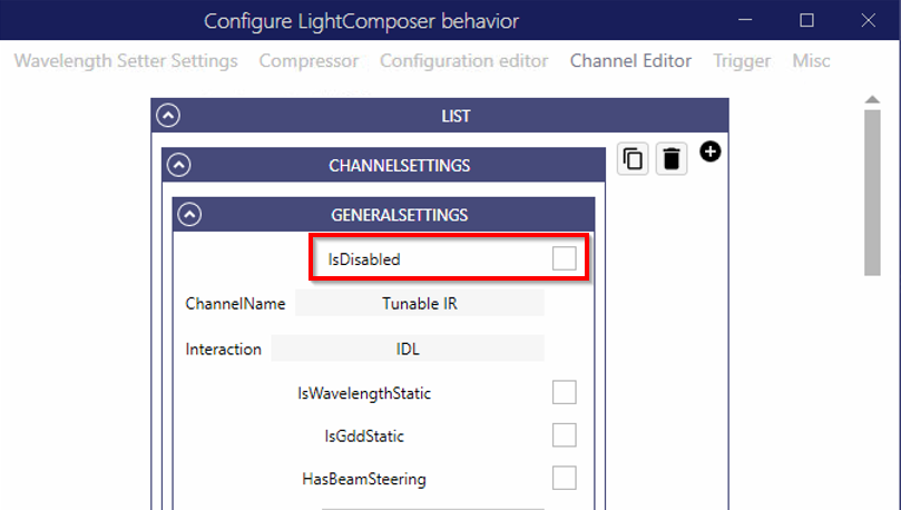
Channels can be disabled in the Channel Editor by changing the value of IsDisabled for a given channel.
Setting up a virtual CRONUS-3P device
A virtual CRONUS-3P device is a server running on a local machine which emulates the laser hardware. All features of a real CRONUS-3P laser are supported, so you can use it to test remote API control.
- Download and install WinTopas4 (WT4) and Light Composer apps.
- Launch WT4 and switch to Advanced user mode.
- Download a virtual CRONUS-3P configuration for a device you want to emulate: IR only, IR+1030 nm, or IR+VIS+1030 nm.
- Start a server using a configuration file in WinTopas4 by selecting Tools -> Launch new device from zipped configuration.
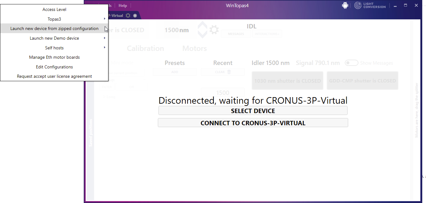
- Click No to run the configuration as a virtual one.

- Launch Light Composer, it should automatically connect to the virtual device server.
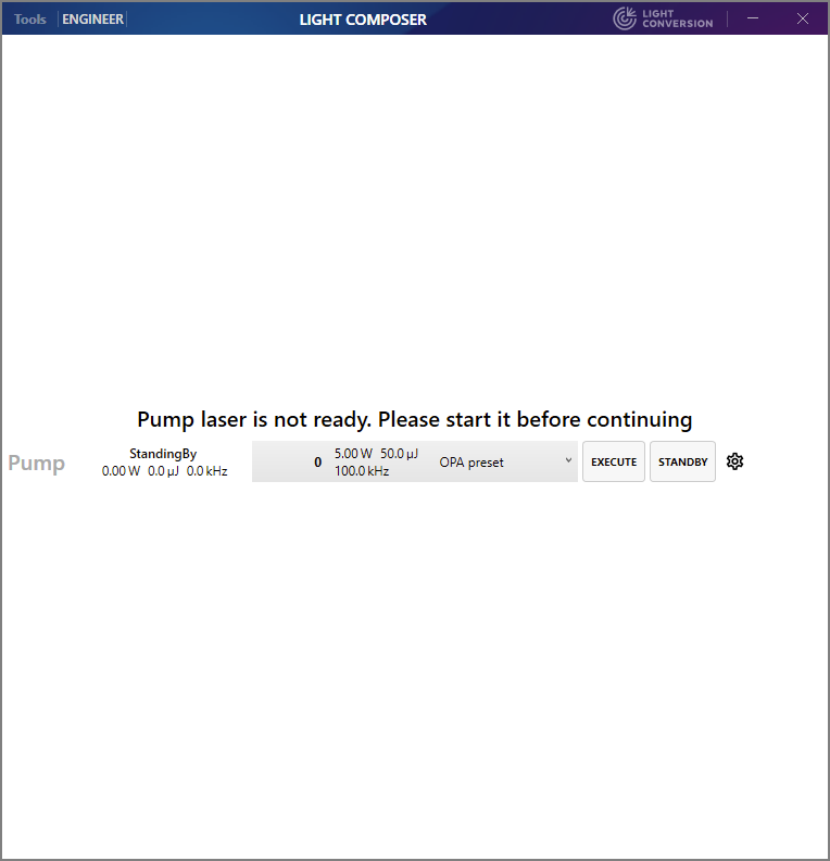
- Once connected, you will see the pump laser screen, click Execute to start the laser.
- The virtual CRONUS-3P is now running, you can test GUI functions and the app will respond to API commands.
Running an existing physical device configuration in virtual mode
There several caveats to run a physical device configuration in virtual mode:
- Laser preset requirements must be disabled in WT4
- Beam steering type must be changed to Dummy in Light Composer Settings.
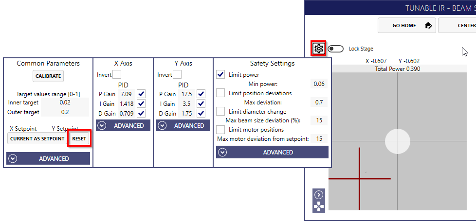
- Beam position sensor offsets are not supported and must be set to zero by clicking Reset in the Common Parameters section for each sensor in the Beam Steering window for every channel that has beam steering.
API Control
Light Composer provides an API service for remote control, automation and advanced applications. Light Composer operates on top of the Topas4 server which performs the actual hardware control. Some use cases and engineering tasks can be achieved using WinTopas4, which is a GUI-based application tailored for laser engineers.
WinTopas4 is not required to run Light Composer, but a Topas4 server is. When Light Composer is started it should also start the Topas4 server. Topas4 also provides an API with more functionality, e.g., low level motor control. It is recommended to utilize Light Composer API first and only turn to Topas4 API if the task cannot be achieved with Light Composer API alone.
Light Composer API online documentation can be found here. You can also access offline API documentation on the same machine that runs Light Composer. The URL contains the server IP address, the device SN and port. In this example the IP is localhost (127.0.0.1), SN is C3PV2-Virtual, and port is 35120.:
- Offline API root: http://127.0.0.1:35120/C3PV2-Virtual/v1/
- Main section: http://127.0.0.1:35120/C3PV2-Virtual/v1/Main/Help
- Channel section: http://127.0.0.1:35120/C3PV2-Virtual/v1/help
Topas4 offline API documentation can be found at the same IP, but different URL and ports. Note, that the ports are different for the root page (default 8002) and the individual sections (default 8000):
- Offline API root: http://127.0.0.1:8002/C3PV2-Virtual/Main.html#PublicAPI
- Motors section: http://127.0.0.1:8000/C3PV2-Virtual/v0/PublicAPI/Motors/help
Remote/API control warning
Remote and API control is performed over the network including the 127.0.0.1 loopback interface and may result in inadvertent remote control of a laser located in another room or building. Possible remote control effects include starting and stopping the laser, opening or closing shutters, laser parameter change (e.g., wavelength, GDD, repetition rate, and power).
Inadvertent remote control usually requires the following conditions to be met: * the device IP address is set incorrectly * the remote device SN happens to be correct, e.g., the name is a common or default value or the device has been moved to a different location but the remote control code has not been updated * the remote device has enabled remote control from the host issuing the remote commands, e.g., the remote connection has been used previously and is allow-listed
Running the script with the device IP address set to localhost (127.0.0.1) is generally safe and should only control a laser that is locally connected to this machine.